Pid Regulyator Na Arduino

Learn to implement the widely used industrial controller on the Arduino platform! (For students, makers, and engineers) - Free Course. This PID controller device consists of three sub-units: an Arduino Uno R3; MAX6675 thermocouple temperature sensor; and1602 LCD keypad display.

The WriteRegister() function is used to write data to the Firstbot’s PIC16F1829 microcontroller registers. The Firstbot has two microcontrollers on board. One operates as an Arduino Uno.
The other uses the same communication protocol as our BM011. WriteRegister() matches the communication protocol that is defined in the Firstbot datasheet.
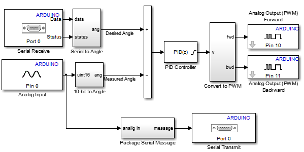
The PIC16F1829 controls 2 H-bridges and can output 4 RC style pulses. It can also read RC style pulses. In the case of this application the PID algorithm is being handled by the Arduino Uno and WriteRegister() is used to control the PWM output of one of the H-bridges connected to the PIC16F1829. Take a look at the Firstbot datasheet for more clarification (should be a link in the blog post). I think for(i=0; i. A few people have pointed out errors in the D term loop (quite a while ago). I thought I changed the code in the post to sort down and not up.
I couldn’t find the code you posted in the blog I think for(i=0; i 0;i–) Error[i] = Error[i-1]; Somebody also pointed out that you don’t need an array of errors in the D term implementation. You can just have two variables Previous_Error and New_Error. The D part of the PID is calculated by PID += DTerm*(New_Error-Previous_Error) I have found that in some motor control applications the difference in error terms between two PID updates is pretty small. At times it helps to track errors over a longer time frame to apply damping to step effects from sudden position changes. I like to read this code for controlling the servo by PWM but i need more clarify or to solve my confusing for me come from the following: 1- the calculating error of the desired and measured signal what the dimension of it (degrees, mdegrees,.) 2- the controller gains it is in order of thousands like P=2000, 3- the output of PID divided by 10 divider how to calculate the divider 3- the out of PID to get the PWM output added 127 is it in msec 4- the range of servo from 1 to 254 is it in ms also thanks.
Hi Alaa, Here are some responses 1: The error signal initially would have the units of what is being measured, in this case volts. But the error signal is converted to PWM by the PID process, so I guess in this case I guess it becomes direction and duty cycle of motor speed (which I guess is pretty much still volts). 2-3: You could use floating point math to have the gains look more like 1.0 or 0.0055. In the end I was trying to achieve a few things. First, the proportional gain will probably be the largest of the PID, and it needs to act on small error signals. Second, the I term needed to have some effect, but not so much as to cause chatter or windup. Third, the input error signal needed to scale roughly to the output I needed.
Ea sports cricket 2012 game free download for android. EA Sports Cricket 18 Free Download PC Game Android APK. EA Sports Cricket 2018 has real cricket tournament interface with all world-famous cricket teams and players. The game has a different type of gameplay Career Mode, and Multiplayer mode in online and on console two players can challenge each other.
Depending on your system the I and D terms may not even be used. Whatever error signals in a system requires the PID output to be scaled to be pretty close to the desired drive signal. The gain settings are, in this case, based on the type of variable used in the system (int and long), and some trial and error. The divider I used is a divide-by-two (right rotate).
Our error signal is 10 bits and our gain is about 9 bits, so I used those magnitudes as an estimate for the divider’s number of rotates. 3-4 You can take a look at the FirstBot datasheet on PWM frequency. The Firstbot accepts an 8-bit speed and direction value with 127 being stopped.
So these values are not mS. They translate to duty cycle and direction. 127 being 0% on, 254 being 100% on, and 1 being -100% on (reverse full speed). Christopher, You’ll need to get the digital encoder signals into the Arduino. We of use the LS7083 to do this (an LSI part sold by US Digital in the US). This can also be done with logic chips. I usually design with Microchip’s PIC controllers where the encoder A and B channels can be fed into external clock hardware.
I’m not sure which Arduino style has these features so you have to look around for examples. Once you have the encoder channel up and down count in the code your position becomes “up count – down count”. This then becomes the actual position in the PID code. The pot analog conversion becomes your desired position.
Kutools for excel crack. • Also, Listing all worksheet names of a workbook inside pane. • Listing all columns and titles of a worksheet inside pane. • So, Decrease the ribbon, conceal the standing bar, components bar and ribbon with one click on. • Decrease the ribbon with one click on.